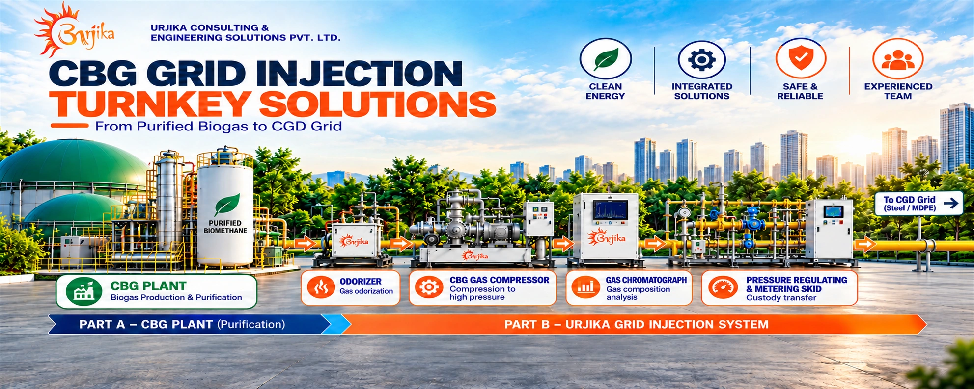

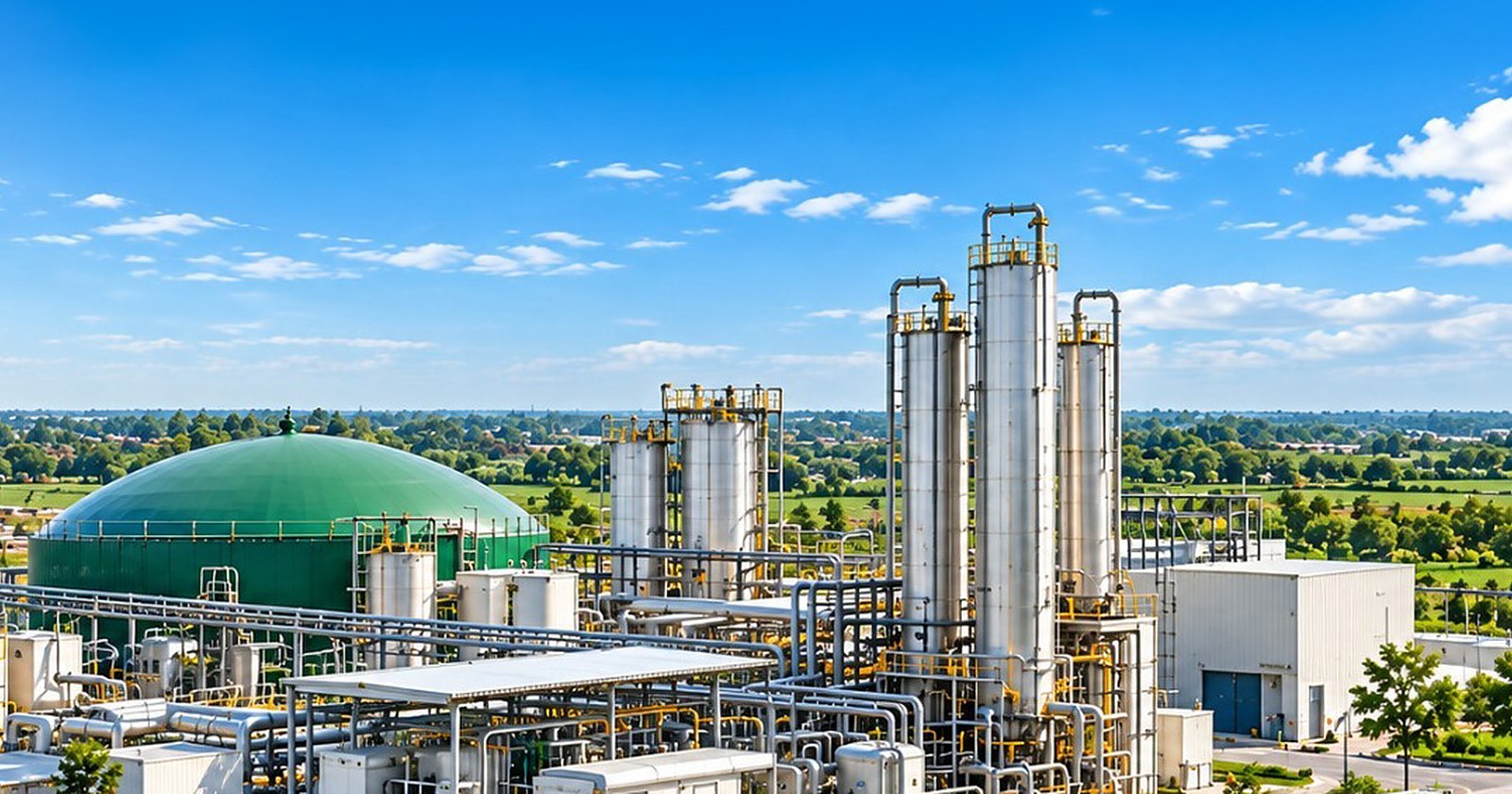
CBG Grid Injection Turnkey Solutions — from purified biogas to the CGD grid through odorizer, CBG gas compressor, gas chromatograph and pressure regulating and metering skid

CBG Grid Injection Turnkey Solutions

One integrated solution — from purified biogas to the CGD grid.

End-to-end CBG grid injection: odorization, compression, online gas quality analysis, pressure regulation, metering and custody transfer — engineered, automated and commissioned by Urjika.

Feb 2026
PNGRB guidelines for CBG injection into CGD & NGPL networks
3 – 5 bar
Typical injection into MDPE networks
≥ 90% CH₄
Biomethane quality as per IS 16087
24 × 7
Automated monitoring with auto-isolation
Overview

Evacuate your CBG through the pipeline — not the highway

Urjika provides end-to-end CBG grid injection solutions, connecting purified biogas to city gas distribution networks through integrated odorization, compression, gas quality analysis, pressure regulation, metering and custody transfer systems.

Injecting directly into the CGD network removes the cost and risk of trucking cascades, gives producers an assured offtake route and lets CBG reach PNG and CNG customers seamlessly. In February 2026, PNGRB approved dedicated guidelines for CBG injection into CGD and natural gas pipeline networks — covering gas quality, analysers, odorization, pressure regulation, metering and safety. Our systems are engineered around these requirements.

Evacuation routes

Four ways to take CBG to market

Direct injection — CGD MDPE network
Compression to approx. 3–5 bar, quality monitoring, odorization, PRS and metering, injected into the PE network.
Direct injection — CGD steel / NGPL
Compression to the operating pressure of the steel network, within its maximum allowable operating pressure.
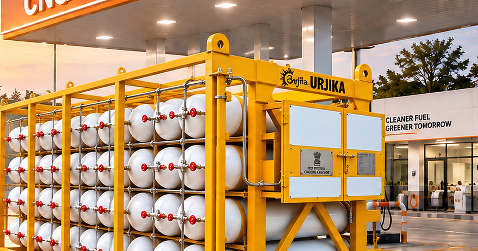
Mobile cascades to CNG stations
CBG compressed to 200–250 bar and dispatched in cascades for dispensing at retail outlets.
Cascade to DCU injection
Cascades delivered to a decompression station that injects gas into CGD or NGPL networks.
Grid injection system

How purified CBG reaches the city gas network

Every stage is monitored by a central PLC. If gas quality, pressure or odorization moves outside limits, the system isolates injection automatically.

01
Purified CBG inlet (VPSA 0.1–0.3 bar / membrane 8–12 bar)
02
Online GC & dew-point analysis
03
Auto diverter — off-spec gas recycled
04
Proportional odorization
05
Fine filtration (5 micron)
06
Compression to grid pressure
07
PRS — active/monitor + SSV + CRV
08
Metering with EVC → CGD grid
System overview

Part A: CBG plant · Part B: Urjika grid injection system
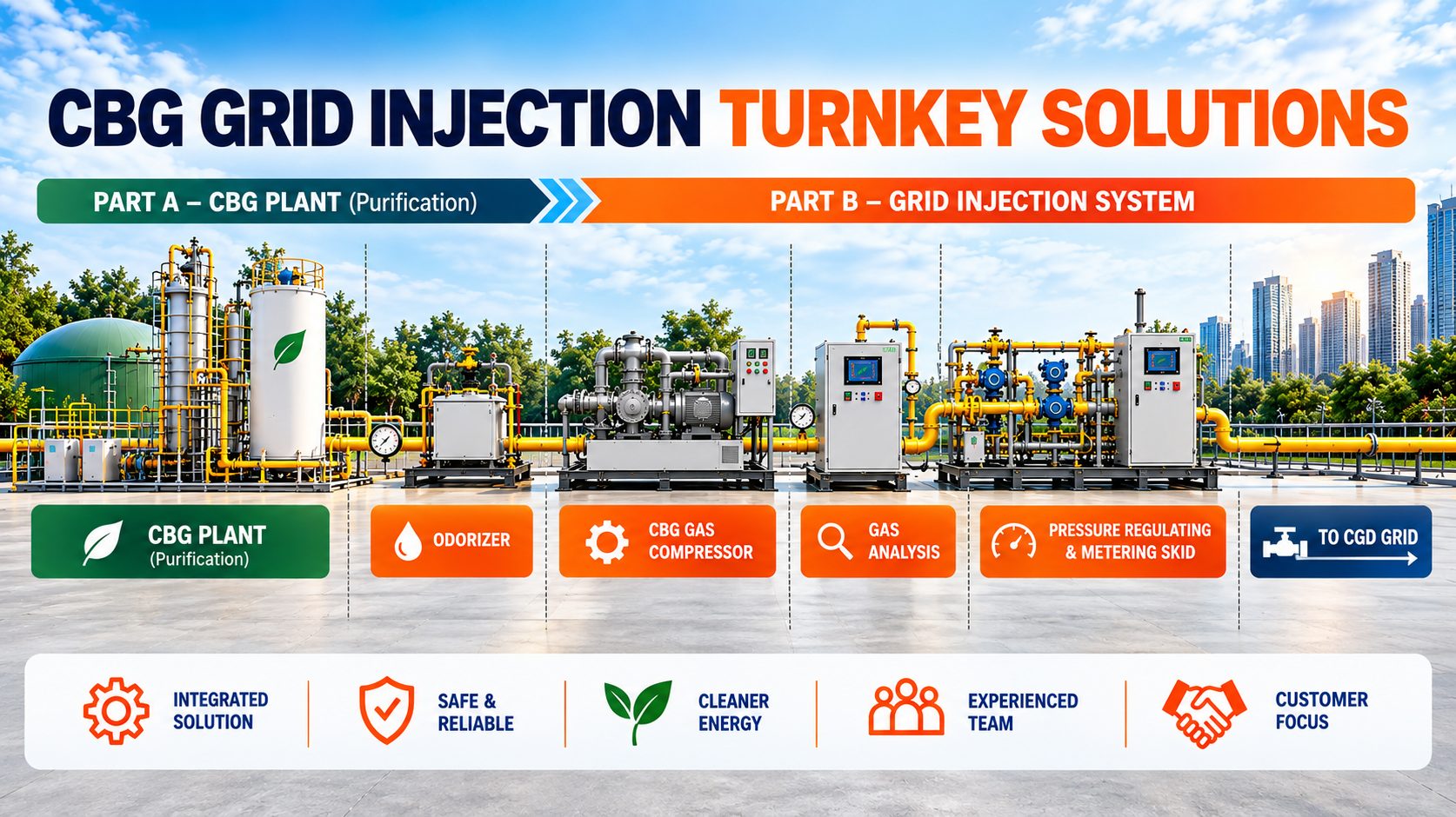
Part A: CBG plant  ·  Part B: Urjika grid injection system
Equipment

What goes into an Urjika grid injection system

CBG Gas Compressor
Raises purified gas from 0.1–0.3 bar (VPSA) or 8–12 bar (membrane) to grid injection pressure — up to 49 bar for steel networks.
Odorizer
Skid-mounted, PLC-controlled dosing of Ethyl Mercaptan or TBM+MES, proportional to real gas flow.
Online Gas Chromatograph
Measures CH₄, CO₂, O₂, N₂, H₂S and calculates GCV, NCV, relative density and Wobbe index (ISO 6976).
Moisture / Dew-Point Analyser
Confirms water and hydrocarbon dew point stays at or below 0°C at pipeline pressure.
H₂S Analyser
Continuous sulphur monitoring to protect the network and end users.
Automated Diverter Valve
Motorised / pneumatic 3-way valve that recycles off-spec gas back to the plant instead of the grid.
Filter / Separator
High-efficiency 5-micron filtration with differential pressure monitoring.
Pressure Regulating Skid
Active–monitor regulation with slam-shut valve, creep relief valve, NRV and vent — single or twin stream.
Metering Skid with EVC
Custody transfer metering with electronic volume correction; twin-stream configuration; flow signal shared for odorant dosing.
Skid Automation — PLC / SCADA
Central PLC with HMI, interlocks, data logging and Modbus / Ethernet link to the CGD control room.
Gas Detection & ESD
Fixed methane detectors (alarm at 20% LEL, isolation at 40% LEL), emergency stop push buttons and ROV.
UPS & Power Back-up
Uninterrupted power for GC, analysers and control panel so monitoring never stops.
Automatic isolation

Injection stops automatically when…

These automatic isolation triggers follow the PNGRB guidelines for CBG injection.

Delivery pressure deviates
Redundant pressure monitoring keeps injection within the pipeline’s MAOP.
Gas quality goes off-spec
CH₄, dew point or other parameters move outside agreed limits.
Odorization fails
Odorant dosing is not being done as specified.
GC / analyser loses power
Quality cannot be verified, so injection is isolated.
Methane leak detected
Gas detector reading above 40% LEL.
Emergency stop pressed
ESD push buttons at control room, process area and equipment.
Quality & monitoring

Gas quality parameters we monitor

Gas composition
Methane (CH₄)
Minimum 90% by volume (IS 16087)
Carbon dioxide, oxygen, nitrogen
Within IS 16087 and network access-code limits
Hydrogen sulphide & total sulphur
Continuously monitored
Moisture
Moisture analyser at plant
Siloxanes / others
Additional analysers if required by the CGD entity
Network requirements
Water & hydrocarbon dew point
≤ 0°C at pipeline operating pressure
Gas temperature
Maximum 55°C
Energy parameters
GCV, NCV, relative density, Wobbe index (ISO 6976)
GC method
As per ISO 6974 and IS 16087
Sampling frequency
As required by the injection agreement (typically every 5 minutes)
Data & calibration
Data logging
Historical trends stored locally and remotely
Remote access
Web / SCADA link shared with the CGD operator
Communication
Modbus with spare RS485 / Ethernet port
Calibration
Periodic calibration with certified gas
Meter calibration
At ISO 17025 accredited labs
Safety & compliance
Design basis
PNGRB T4S regulations for CGD / NGPL
Hazardous area
Classification as per IS 5572; equipment to IS/IEC 60079
Studies
HAZOP and QRA support
Venting
Controlled vents min. 3 m above platform
Approvals
PESO licensing and CGD entity approvals support
Reference configuration

Typical grid injection project (2 TPD CBG plant)

ParameterValue
Plant capacity2 TPD CBG
Injection flow rate200–220 SCMH
Inlet pressure from purification0.2–0.4 bar
Compressor0.2 bar → up to 6 bar
PRSInlet 6 bar, outlet 5 bar, PCV + slam-shut (OPSP 6 bar)
Filtration5-micron filter with DP transmitter
MeteringFlow meter with electronic volume corrector
Quality monitoringOnline gas chromatograph + dew-point analyser at inlet
Off-spec handlingAutomated 3-way valve recycles poor-quality gas to recovery line
Process piping2" CS Sch 80; 4" outlet line
NetworkMDPE pipeline, 3–5 bar
ControlCentral PLC with pressure transmitters and interlocks

Configuration shown is indicative. Each system is engineered to the plant capacity, purification technology and the CGD entity’s injection agreement.

Urjika scope

Turnkey — from concept to commissioning

01
Engineering
Process design and P&ID
Equipment sizing and layout
Hazardous area classification
HAZOP / QRA support
Interface with CGD entity
02
Equipment supply
Compressor and odorizer
GC, dew-point and H₂S analysers
PRS, metering skid with EVC
Filters, valves and SS / CS piping
PLC / SCADA panel and UPS
03
Execution & commissioning
Installation and tubing / piping works
Automation and interlock testing
Calibration and trial injection
Documentation and approvals support
Operator training and O&M support
FAQ

Frequently asked questions

Q.What pressure is CBG injected at?
Typically about 3–5 bar into MDPE CGD networks. For steel networks and NGPL, injection pressure matches the operating pressure of the pipeline, within its maximum allowable operating pressure.
Q.Can I inject without a pipeline connection at my plant?
Yes. CBG can be compressed into mobile cascades and injected into the network through a decompression (DCU) station.
Q.Which regulations apply?
PNGRB guidelines for CBG injection (Feb 2026), PNGRB T4S regulations for CGD / NGPL, access-code quality specifications and IS 16087 for biomethane quality.
Q.What happens if gas quality drops?
The online GC and analysers detect it and the PLC automatically diverts or isolates the gas, so off-spec gas never enters the grid.
Q.Is odorization required?
Yes, for injection into CGD networks. Odorant is dosed in proportion to measured flow, preferably using the same odorant as the CGD entity.
Q.Can Urjika work with our existing purification supplier?
Yes. Our grid injection system starts at the outlet of your VPSA or membrane purification and integrates with your plant controls.

Ready to inject CBG into the grid?

Let’s engineer a safe, compliant grid injection system for your plant.
Explore more

Other solutions